Up to 600 N
High linear thrust
A robust 42 mm motor platform supports demanding push-pull positioning tasks when paired with the correct lead and drive profile.
42 mm linear motion platform
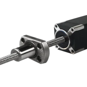
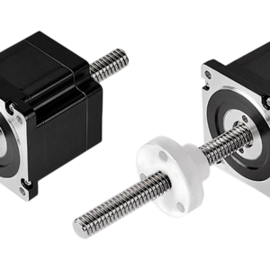
The SP42SLA 42 mm sliding lead screw linear actuator converts stepper-motor rotation into controlled linear travel for industrial mechanisms that require compact packaging, repeatable positioning and flexible mechanical integration. Select the motor winding, screw lead and output configuration to match the required thrust, speed and installation envelope.
A robust 42 mm motor platform supports demanding push-pull positioning tasks when paired with the correct lead and drive profile.
Available lead values span 0.6096 to 25.4 mm, allowing engineering trade-offs between travel per step, speed and axial force.
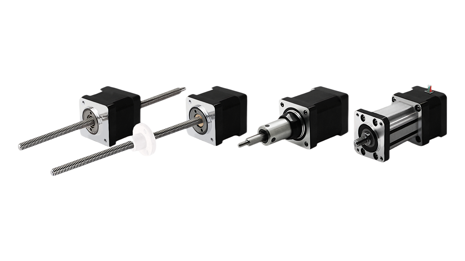
External-drive, through-shaft, C-type fixed-shaft and K-type fixed-shaft layouts cover a broad range of guided linear mechanisms.
Technical data
Electrical platform
| Winding | Phase voltage | Phase current (RMS) | Phase resistance | Phase inductance | Weight | Leads | Motor length |
|---|---|---|---|---|---|---|---|
| 17-2105 | 7.2 V | 0.5 A | 14.4 Ω | 19.8 mH | 254 g | 4 | 34.1 mm |
| 17-2110 | 3.8 V | 1.0 A | 3.8 Ω | 5 mH | 254 g | 4 | 34.1 mm |
| 17-2115 | 2.85 V | 1.5 A | 1.9 Ω | 2.2 mH | 254 g | 4 | 34.1 mm |
| 17-2205 | 11 V | 0.5 A | 22 Ω | 46 mH | 386 g | 4 | 48.1 mm |
| 17-2212 | 4.5 V | 1.2 A | 3.8 Ω | 8 mH | 386 g | 4 | 48.1 mm |
| 17-2225 | 2.5 V | 2.5 A | 1 Ω | 1.8 mH | 386 g | 4 | 48.1 mm |
Class B insulation. Rated temperature rise: 80 °C. Recommended ambient operating range: −20 to +55 °C.
Linear travel selection
| Screw Ø (in) | Screw Ø (mm) | Lead (in) | Lead (mm) | Lead code | Travel at 1.8° (mm) | Travel at 0.9° (mm) |
|---|---|---|---|---|---|---|
| 0.25 | 6.35 | 0.024 | 0.6096 | AA | 0.003048 | 0.0015 |
| 0.236 / 0.25 / 0.315 | 6 / 6.35 / 8 | 0.0394 | 1 | AB | 0.005 | 0.0025 |
| 0.25 | 6.35 | 0.025 | 0.635 | A | 0.003175 | 0.0015 |
| 0.25 | 6.35 | 0.048 | 1.2192 | B | 0.006 | 0.003 |
| 0.25 | 6.35 | 0.05 | 1.27 | D | 0.0064 | 0.0032 |
| 0.25 | 6.35 | 0.0625 | 1.5875 | F | 0.0079 | 0.004 |
| 0.25 | 6.35 | 0.096 | 2.4384 | J | 0.0122 | 0.0061 |
| 0.25 | 6.35 | 0.1 | 2.54 | K* | 0.0127 | 0.0064 |
| 0.25 | 6.35 | 0.125 | 3.175 | L* | 0.0159 | 0.0079 |
| 0.25 | 6.35 | 0.192 | 4.8768 | Q | 0.024 | 0.0122 |
| 0.25 | 6.35 | 0.2 | 5.08 | R* | 0.0254 | 0.0127 |
| 0.25 | 6.35 | 0.25 | 6.35 | S* | 0.0318 | 0.0159 |
| 0.25 | 6.35 | 0.3333 | 8.4667 | U | 0.0423 | 0.0212 |
| 0.25 | 6.35 | 0.384 | 9.7536 | W* | 0.0488 | 0.0244 |
| 0.25 | 6.35 | 0.5 | 12.7 | Y* | 0.0635 | 0.0318 |
| 0.25 | 6.35 | 1.0 | 25.4 | Z* | 0.127 | 0.0635 |
| 0.25 | 6.35 | 0.0313 | 0.794 | N | 0.00397 | 0.002 |
| 0.315 | 8 | 0.1575 | 4 | M | 0.02 | 0.01 |
| 0.315 | 8 | 0.315 | 8 | T | 0.04 | 0.02 |
| 0.25 / 0.315 | 6.35 / 8 | 0.0787 | 2 | G | 0.01 | 0.005 |
| 0.236 / 0.315 | 6 / 8 | 0.1969 | 5 | E | 0.025 | 0.0125 |
| 0.315 | 8 | 0.3937 | 10 | C | 0.05 | 0.025 |
Values marked with an asterisk are rounded. Winding and screw length can be configured to order. External-drive assemblies can also be evaluated with a 9.525 mm screw.
Mechanical platform
| Configuration | Motor stack | Screw diameter | Integration note |
|---|---|---|---|
| External drive | 34.1 or 48.1 mm motor stack | 6, 6.35 or 8 mm; optional 9.525 mm | Lead screw translates while the nut is supported by the application |
| Through shaft | 34.1 or 48.1 mm motor stack | 6, 6.35 or 8 mm | Compact translating-screw arrangement through the motor axis |
| C-type fixed shaft | 34.1 or 48.1 mm motor stack | Configuration-dependent | Integrated fixed-shaft output for guided linear mechanisms |
| K-type fixed shaft | 34.1 or 48.1 mm motor stack | Configuration-dependent | Fixed-shaft assembly for supported loads and custom couplings |
Dimensions A, B, C and L are configuration-dependent. Confirm the selected lead, stroke, end machining and load guidance before release.
Feedback options
| Encoder | Output | Available resolution | Mechanical format |
|---|---|---|---|
| EK1 | Single-ended / differential | 100, 108, 120, 125, 128, 200, 250, 256, 300, 360, 400, 500, 512, 720, 800 or 1000 CPR | Compact round encoder |
| EK2 | Single-ended / differential | 50, 100, 192, 200, 250, 256, 360, 400, 500, 720, 900, 1000, 1250, 2000, 2500, 4000 or 5000 CPR | Extended housing encoder |
| EK7 | Single-ended / differential | 1000 or 2000 CPR | Low-profile square encoder option |
Encoder availability and mounting dimensions depend on the selected motor stack and rear accessory package.
Holding option
| Parameter | Value |
|---|---|
| Series | 42 mm |
| Rated voltage | 24 VDC ±5% |
| Resistance | 145 Ω ±10% |
| Power | 5 W |
| Static torque | > 0.8 N·m |
| Insulation class | Class B |
| Insulation resistance | > 100 MΩ at 500 VDC |
| Dielectric strength | 1000 VAC for 1 s |
| Pull-in time | 50 ms |
| Release time | 50 ms |
| Rotational clearance | 1° |
| Emergency braking | 200 cycles |
| Mechanical life | 500,000 cycles |
| Noise | < 60 dB(A) |
The brake is intended to hold a stationary axis after power removal. Emergency-braking limits and thermal duty must be reviewed for the application.
Mechanical drawings
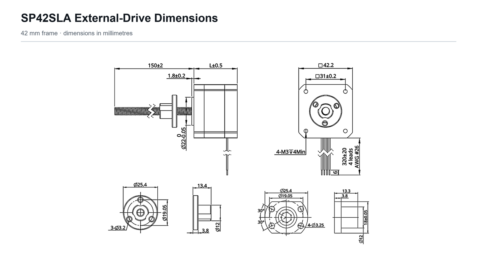


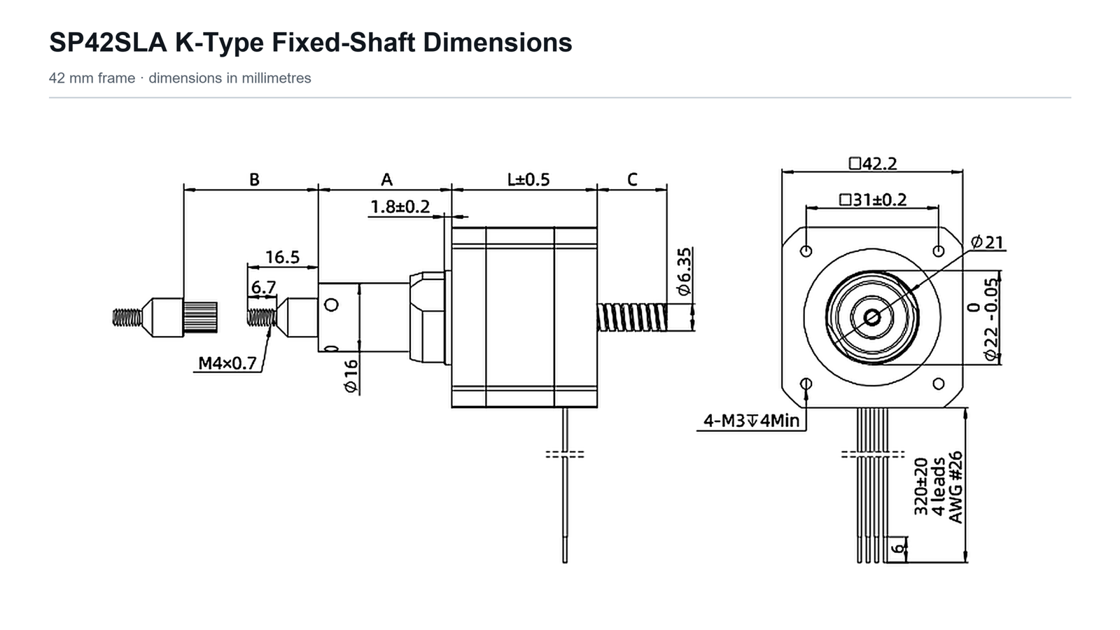
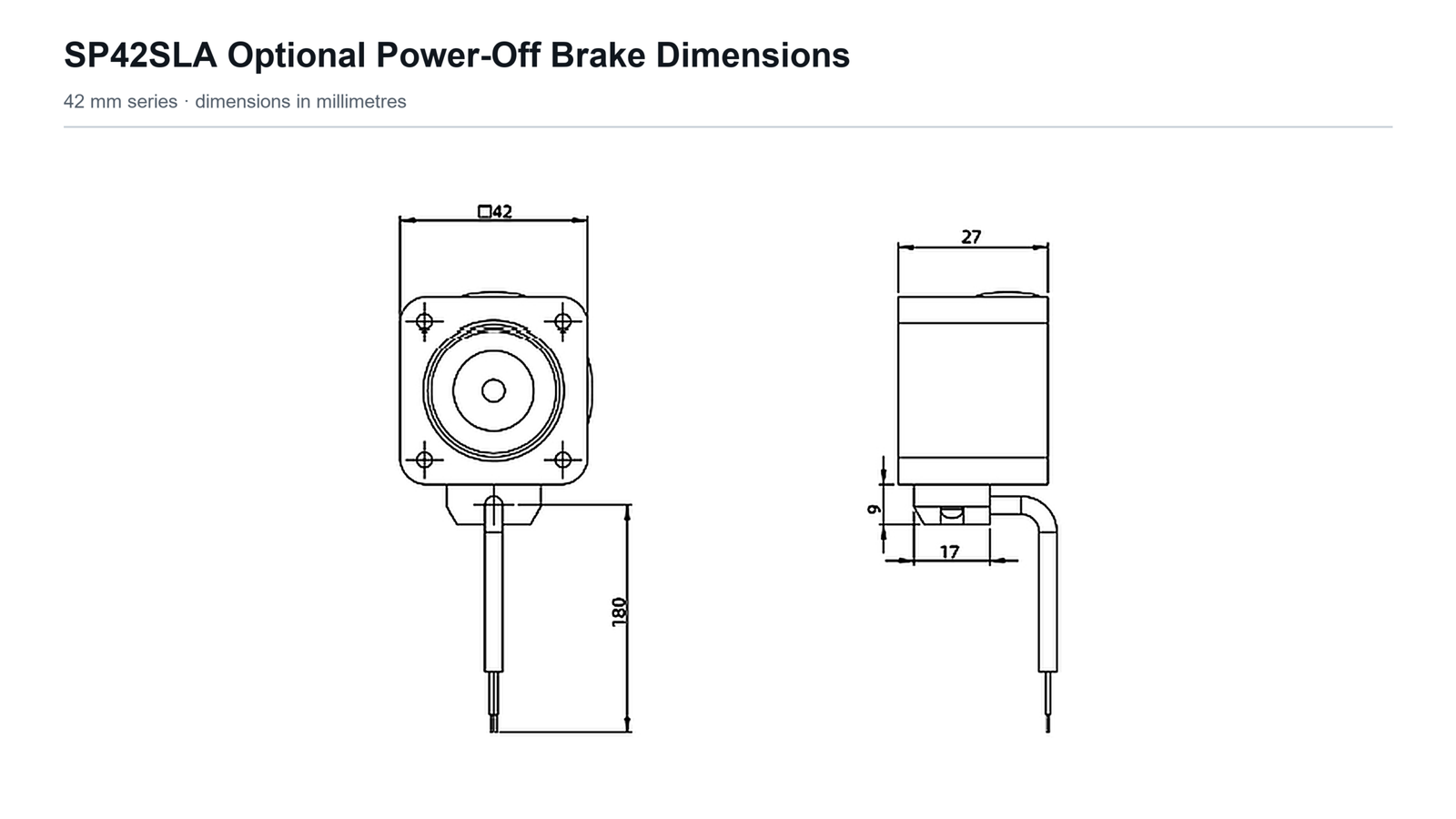
Performance reference
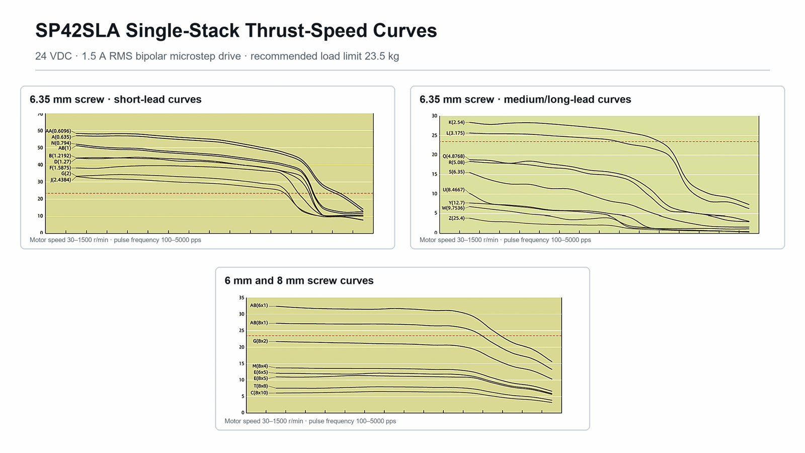
Application-ready integration
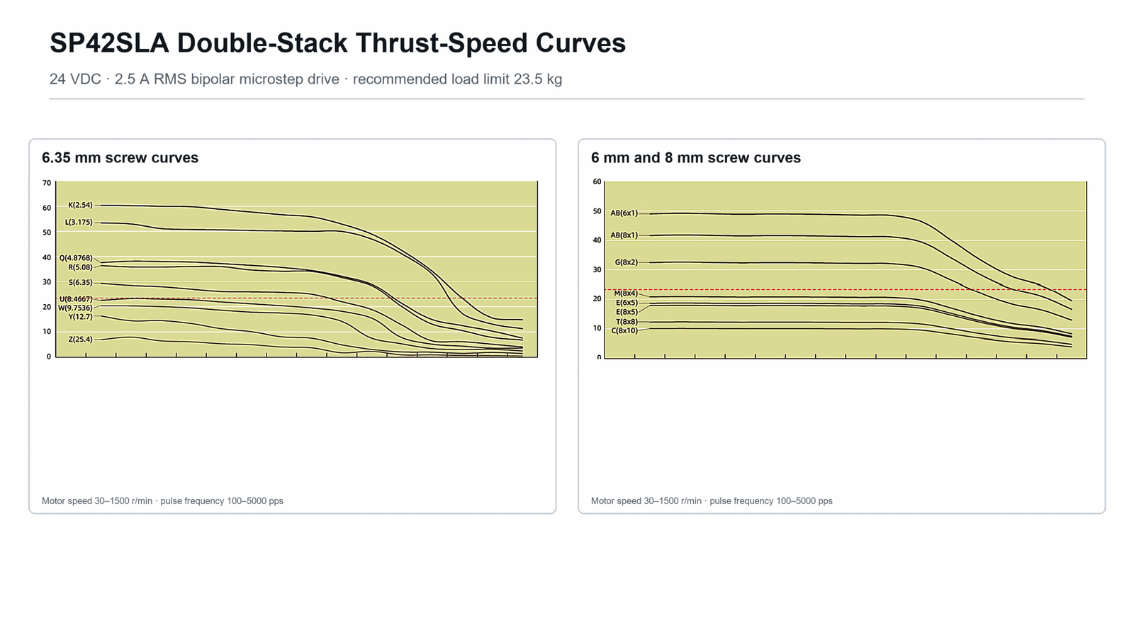
Lead choice sets the basic balance between speed, resolution and force. Reliable machine performance also depends on drive current, acceleration, external guidance, screw support, lubrication strategy and operating duty.
Typical applications
SP42SLA is suited to guided axes where compact geometry, configurable travel and controllable thrust are more important than a fully enclosed actuator package.
Wafer-handling modules, inspection fixtures, test equipment and precision component positioning.
Sample-handling mechanisms, optical adjustment, fluid-control positioning and automated analysis systems.
Dispensing, labeling, packaging, pick-and-place tooling, valve adjustment and compact transfer mechanisms.
Focus adjustment, sensor positioning, calibration fixtures and compact scientific motion modules.
Selection guidance
For a reliable recommendation, provide the required stroke, thrust, target speed, duty cycle, installation orientation, available supply voltage, positioning resolution and environmental conditions.
Configure SP42SLA
Send the stroke, load, speed, duty cycle and installation constraints. Spotlight Motor can help match the winding, lead, mechanical layout and feedback package.