

SPYCSV40 40 mm Hollow Shaft Servo Motor
Frame Size
40 mm
Rated Power
100 W
Rated Torque
0.32 N·m
100 W through-bore servo motor with a Ø4.2 mm axial passage, 24/48 VDC windings and selectable feedback.
SPYCSV hollow shaft servo motors combine closed-loop motion with a central passage for wiring, tubing or coaxial integration. Choose 40, 60, 80 or 110 mm frames, with rated power from 100 to 1500 W and rated torque from 0.32 to 5.7 N·m. Through-bore, winding and feedback configurations are matched to the application.
Compare 24/48 VDC, 220 VAC and 380 VAC motor variants below, then confirm the mounting envelope, operating point, compatible servo drive and connection details for your rotary axis.

Open each product for detailed electrical data, mechanical drawings and configuration information.
100 W through-bore servo motor with a Ø4.2 mm axial passage, 24/48 VDC windings and selectable feedback.
200–600 W servo motor with Ø10/Ø12 mm bore configurations, 48 VDC or 220 VAC windings and selectable feedback.
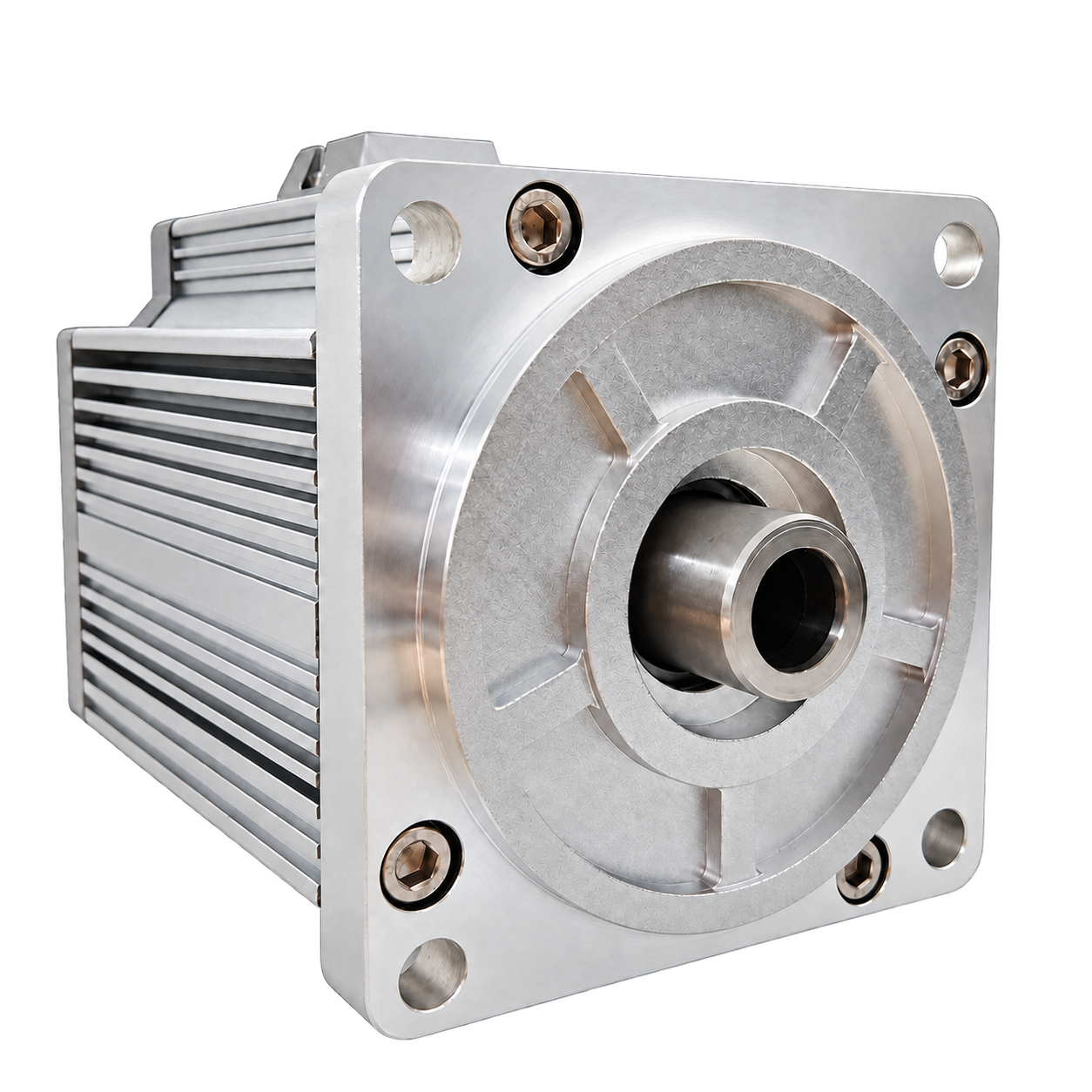
750 W servo motor with a Ø10 mm through bore, 2.4 N·m rated torque and 48 VDC, 220 VAC or 380 VAC winding choices.

800 W or 1500 W servo motor with a Ø20 mm through bore, 5–5.7 N·m rated torque and 48 VDC or 220 VAC winding choices.
Select by torque and speed as well as power. Voltage designations identify motor variants; operation requires a compatible servo drive.
| Motor variant | Voltage | Rated power | Rated torque | Rated speed | Max. speed |
|---|---|---|---|---|---|
| SPYCSV40B-100 | 24 VDC | 100 W | 0.32 N·m | 3000 rpm | 5000 rpm |
| SPYCSV40D-100 | 48 VDC | 100 W | 0.32 N·m | 3000 rpm | 3850 rpm |
| SPYCSV60D-200 | 48 VDC | 200 W | 0.64 N·m | 3000 rpm | 3850 rpm |
| SPYCSV60L-200 | 220 VAC | 200 W | 0.64 N·m | 3000 rpm | 5000 rpm |
| SPYCSV60L-240 | 220 VAC | 240 W | 1.91 N·m | 1200 rpm | 5000 rpm |
| SPYCSV60D-400 | 48 VDC | 400 W | 1.28 N·m | 3000 rpm | 3850 rpm |
| SPYCSV60L-400 | 220 VAC | 400 W | 1.27 N·m | 3000 rpm | 5000 rpm |
| SPYCSV60D-600 | 48 VDC | 600 W | 1.91 N·m | 3000 rpm | 3850 rpm |
| SPYCSV60L-600 | 220 VAC | 600 W | 1.91 N·m | 3000 rpm | 5000 rpm |
| SPYCSV80D-700 | 48 VDC | 750 W | 2.4 N·m | 3000 rpm | 3850 rpm |
| SPYCSV80L-700 | 220 VAC | 750 W | 2.4 N·m | 3000 rpm | 5000 rpm |
| SPYCSV80H-700 | 380 VAC | 750 W | 2.4 N·m | 3000 rpm | 5000 rpm |
| SPYCSV110D-800 | 48 VDC | 800 W | 5 N·m | 1500 rpm | 3500 rpm |
| SPYCSV110L-1500 | 220 VAC | 1500 W | 5.7 N·m | 2500 rpm | 3500 rpm |
Maximum speed does not imply rated torque throughout the speed range. Check the selected winding's torque-speed envelope, current and duty cycle. Detailed current, inertia and available operating curves are provided on the product pages.
Nominal frame size is not a mounting dimension. Check the bore, flange, pilot, shaft interface and motor length as one mechanical package.
A 40 × 40 mm flange, Ø30 mm pilot and Ø8 mm shaft outside diameter, with 10 mm shaft extensions at both ends. Suitable for evaluating compact rotary assemblies where a smaller axial passage meets the routing requirement.
The shaft-extension configuration uses a 60.5 × 60.5 mm flange, Ø50 mm pilot and Ø12.7 mm shaft. Its drawing shows four Ø5 mm mounting holes on a Ø70 mm bolt circle and 10 mm shaft extensions at both ends.
The flush-bore configuration uses a Ø12 mm passage, a 60.5 × 60.5 mm flange and four Ø5.5 mm front mounting holes on a Ø70 mm bolt circle. Rear mounting details differ from the shaft-extension format.
The 80 mm platform uses an 80.5 × 80.5 mm flange, Ø70 mm pilot and Ø19 mm shaft outside diameter. Four Ø6.5 mm mounting holes are arranged on a Ø90 mm bolt circle. Confirm final body length for the ordered configuration.
The 110 mm platform uses a 110 × 110 mm flange, Ø55 mm pilot and Ø25 mm shaft outside diameter. The drawing shows four Ø9 mm holes on a Ø130 mm bolt circle and four Ø6.5 mm holes on a Ø66 mm bolt circle. The 800 W and 1500 W configurations have a 150 mm body length without brake.
Confirm final body length, brake and feedback options, cable clearance, and any radial or axial load requirement before releasing the mounting design. A hollow shaft does not itself provide a slip ring or rotary union.
For rotary modules, positioning mechanisms, inspection axes and OEM assemblies, define the complete motion cycle and integration conditions before fixing the motor configuration.
Specify the clear bore, routed service, shaft interface and available space. Include connector clearance, cable bend radius and radial or axial loads for confirmation.
Provide continuous torque, speed, acceleration, load inertia and duty cycle. Check peak demand separately; maximum torque is not a continuous operating rating.
Match winding voltage and current to the servo drive. Confirm resolver, Tamagawa, incremental or BiSS-C feedback compatibility separately from the controller's communication network.
Define brake function, connector format, lead length, cooling and ambient conditions. Special-environment requirements need configuration-specific confirmation rather than assumptions based on frame size.
Key points to clarify when choosing a hollow shaft servo motor.
Start with the required bore and installation envelope, then compare torque and speed in the table above. Check the complete mechanical drawing rather than selecting by rated power alone.
Use a compatible servo drive. The motor voltage designation is not a direct-wiring instruction. Confirm the drive, winding current, feedback and cable requirements as a matched system.
No. Resolver, Tamagawa, incremental encoder and BiSS-C are feedback choices. The motion-control network is a separate drive/controller requirement; confirm both interfaces for the proposed system.
Not necessarily. Check the selected winding's torque-speed envelope and distinguish continuous operation from intermittent demand. Include acceleration, deceleration and dwell time in the required motion profile.
Brake, connector and lead length form part of the complete order configuration. Specify the brake function and confirm its data, final motor length and cable clearance for the agreed build.
Provide a mounting drawing, bore size, voltage, torque, speed and duty cycle. Add load inertia, feedback, brake, connector, cable length and operating-environment requirements where available.
Share your bore, torque, speed, voltage, mounting and feedback requirements. Include a drawing or motion profile where available so the complete motor configuration can be confirmed.
Open full contact page →