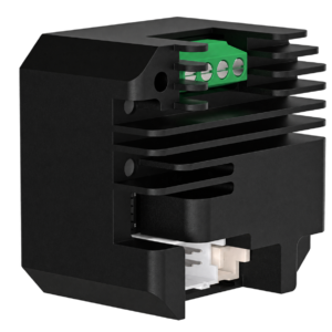
SPBPO422 Pulse-Controlled Open-Loop Stepper Driver

Pulse & Direction Driver
SPBPO422 is a separate pulse-controlled open-loop stepper driver with a 20–40 VDC supply range and 0.1–2.2 A peak output current. It supports single-pulse or dual-pulse control, 16 microstep settings, alarm output and brake control.
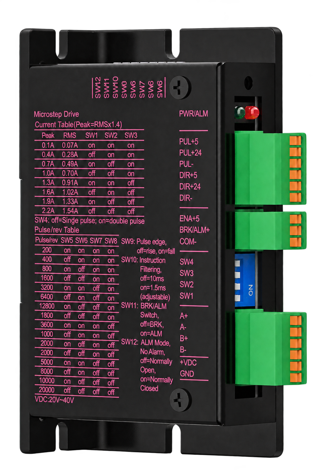
SPBPO422 pulse-controlled open-loop stepper driver with terminal and setting labels

Positioning accuracy

High torsional rigidity and constant torsional backlash over the entire gearbox service life ensure consistently high performance

Compactness

High torque density thanks to high performance and short design

Low maintenance

Highest quality standards for a long service life and extended maintenance intervals

Technical data

Pulse-controlled motion

Adjustable drive control in a separate-driver format

The SPBPO422 open-loop stepper driver combines selectable current and microstep settings with single-pulse or dual-pulse control. A separate driver enclosure keeps drive configuration accessible within the machine’s electrical layout.

Selectable drive settings

Eight current settings cover 0.1–2.2 A peak, while 16 selectable microstep settings allow the drive configuration to be matched to the axis requirement.
Flexible pulse control

Single-pulse and dual-pulse modes support different pulse-command arrangements. The maximum step-pulse input frequency is 200 kHz.

Machine control functions

Alarm output and brake-control functions support system-level coordination. Confirm the external circuit and load requirements before connection.

Engineering information

Technical data

Check the supply range, output-current setting and pulse interface against the motor and controller before selecting the SPBPO422.

20–40 VDCSupply voltage
0.1–2.2 A peakOutput current
200 kHzMaximum pulse frequency
16 settingsMicrostep selection
Electrical

Electrical operating parameters

SPBPO422 electrical operating parameters
Parameter Unit Minimum Typical Maximum
Output current A peak 0.1 — 2.2
Input supply voltage VDC 20 24 40
Step-pulse frequency kHz 0 — 200
Configuration

Drive and control functions

SPBPO422 drive and control functions
Function Specification
Control architecture Separate, open-loop stepper driver
Current selection 8 selectable settings
Microstep selection 16 selectable settings
Command mode Single pulse / dual pulse
Alarm output Supported
Brake control Supported
Interfaces

Terminal identification

SPBPO422 terminal markings
Group Terminal markings
Pulse input PUL+5 / PUL+24 / PUL-
Direction input DIR+5 / DIR+24 / DIR-
Enable / auxiliary ENA+5 / BRK/ALM+ / COM-
Motor connection A+ / A- / B+ / B-
Power input +VDC / GND

Confirm logic-input requirements and brake/alarm output ratings with our engineers before designing the external circuit.
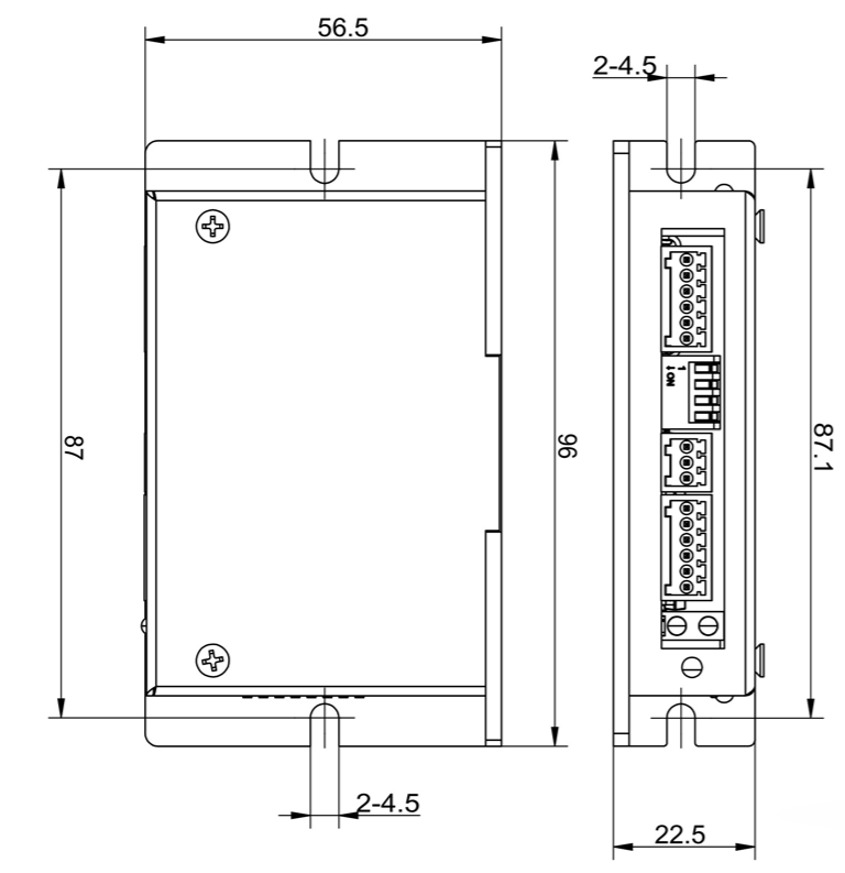
SPBPO422 stepper driver mechanical outline and mounting-slot dimensions
Mechanical outline and mounting slots

Mounting note: the front and side views show 87 and 87.1 for the slot spacing. Confirm the mounting interface and dimension units before machining the installation plate.

Separate drive architecture

Pulse commands. Selectable drive settings.

SPBPO422 provides a separate open-loop drive stage for a pulse-controlled stepper axis. Match the current setting to the selected motor and confirm the pulse mode with the controller.

  • 20–40 VDC supply range with 24 VDC typical input
  • Eight output-current and 16 microstep settings
  • Single-pulse / dual-pulse control, alarm output and brake control
SPBPO422 pulse-controlled open-loop stepper driver
Application selection

Assess the driver against your motion requirements

Use the electrical range and control functions to evaluate the driver for your machine. Motor frame size alone does not establish electrical compatibility.

01

Pulse-command axes

Check the controller’s pulse mode and maximum operating pulse frequency.

02

Separate-driver layouts

Review enclosure space, mounting slots and terminal access in the electrical layout.

03

Motor-current matching

Match the motor winding and rated phase current to an appropriate output-current setting.

04

Auxiliary control

Confirm alarm or brake-control requirements and the external interface before integration.

System integration

Confirm the electrical and mechanical fit

Share the motor data, controller signal details and installation requirements so our engineering team can review the proposed driver configuration.

Power supply20–40 VDC; 24 VDC typical
Output-current range0.1–2.2 A peak
Pulse inputUp to 200 kHz
Control modeSingle pulse / dual pulse
Auxiliary functionsAlarm output and brake control

Discuss your stepper-drive requirement with our engineers.

Send the motor model, rated phase current, supply voltage, pulse-command requirements and installation constraints for selection support.

Request consultation →

Contact us

Would you like to learn more about our solutions?
We would be happy to advise you—personally, competently, and tailored to your requirements.

Perfection in a new dimension

SPBPO422 Pulse-Controlled Open-Loop Stepper Driver
SPBPO422 is a separate pulse-controlled open-loop stepper driver with a 20–40 VDC supply range and 0.1–2.2 A peak output current. It supports single-pulse or dual-pulse control, 16 microstep settings, alarm output and brake control.

Further Information

csm walpha vorzugsbaureihen slider 720x490 eaea48abcd

Short delivery times available for selected product configurations.

csm tp plus image 125ef722c4

The TP+ HIGH TORQUE enables maximum torque density and maximum torsional rigidity—ideal for demanding applications with dynamic load changes and high positioning accuracy.

csm tp plus mf flansch korrosion liegend slider 78e8934f42

alpha Advanced Line gearboxes with increased durability and food-grade lubrication available.

csm tp plus ma rmw ritzel zahnstange slider f4c7f6da40

The TP+ for coordinated pinion-rack systems for medium to high requirements. Typical areas of application in wood, plastic, and composite processing, in machining centers, or in automation.

csm cynapse produkseite element slider 08849abb4c

With cynapse® and smart services, you can unleash the full potential of your drive system: sensor data is processed, visualized, and analyzed intelligently. Find out how the combination of gearboxes with cynapse® and our Smart Services can make your digital production faster, safer, and more efficient.

Related products