Selectable drive settings
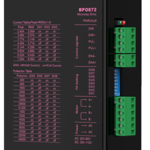
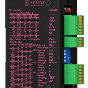
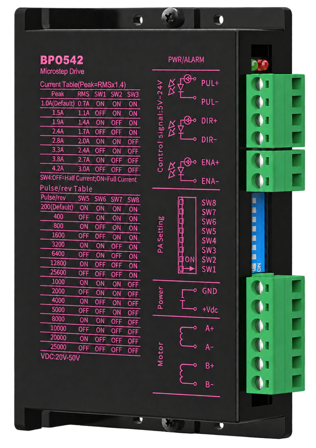
Eight output-current settings span 1.0–4.2 A peak. Select the current and one of 16 microstep settings to suit the motor and motion requirement.
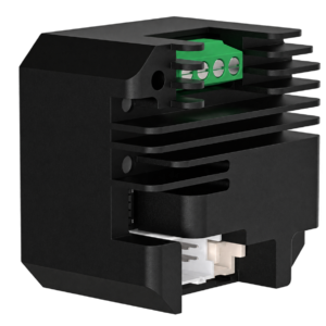
The SPBPO542 open-loop stepper driver combines eight current settings with 16 microstep settings and a dedicated pulse-and-direction interface. Its separate enclosure keeps drive configuration accessible within the machine’s electrical layout.
Eight output-current settings span 1.0–4.2 A peak. Select the current and one of 16 microstep settings to suit the motor and motion requirement.
The pulse input supports frequencies up to 200 kHz. Dedicated PUL, DIR and ENA terminals provide pulse, direction and enable connections.
Control signals are connected separately from motor outputs and the DC supply. The supply range is 20–50 VDC, with 24 or 36 VDC typical input.
Check the supply range, output-current setting and pulse interface against the motor and controller before selecting the SPBPO542.
| Parameter | Unit | Minimum | Typical | Maximum |
|---|---|---|---|---|
| Output current | A peak | 1.0 | — | 4.2 |
| Input supply voltage | VDC | 20 | 24 / 36 | 50 |
| Logic input current | mA | 7 | 10 | 16 |
| Control signal voltage | V | 5 | — | 24 |
| Step-pulse frequency | kHz | 0 | — | 200 |
| Insulation resistance | MΩ | 500 | — | — |
| Function | Specification |
|---|---|
| Control architecture | Separate, open-loop stepper driver |
| Current selection | 8 selectable settings |
| Microstep selection | 16 selectable settings |
| Command interface | Pulse & direction |
| Signal connections | Separate control-signal terminals |
| Group | Terminal markings |
|---|---|
| Pulse input | PUL+ / PUL- |
| Direction input | DIR+ / DIR- |
| Enable input | ENA+ / ENA- |
| Motor connection | A+ / A- / B+ / B- |
| Power input | +Vdc / GND |
SW4: OFF = Half current; ON = Full current.
| Peak current (A) | RMS current (A) | SW1 | SW2 | SW3 |
|---|---|---|---|---|
| 1.0 (default) | 0.7 | ON | ON | ON |
| 1.5 | 1.1 | OFF | ON | ON |
| 1.9 | 1.4 | ON | OFF | ON |
| 2.4 | 1.7 | OFF | OFF | ON |
| 2.8 | 2.0 | ON | ON | OFF |
| 3.3 | 2.4 | OFF | ON | OFF |
| 3.8 | 2.7 | ON | OFF | OFF |
| 4.2 | 3.0 | OFF | OFF | OFF |
| Pulses/revolution | SW5 | SW6 | SW7 | SW8 |
|---|---|---|---|---|
| 200 (default) | ON | ON | ON | ON |
| 400 | OFF | ON | ON | ON |
| 800 | ON | OFF | ON | ON |
| 1600 | OFF | OFF | ON | ON |
| 3200 | ON | ON | OFF | ON |
| 6400 | OFF | ON | OFF | ON |
| 12800 | ON | OFF | OFF | ON |
| 25600 | OFF | OFF | OFF | ON |
| 1000 | ON | ON | ON | OFF |
| 2000 | OFF | ON | ON | OFF |
| 4000 | ON | OFF | ON | OFF |
| 5000 | OFF | OFF | ON | OFF |
| 8000 | ON | ON | OFF | OFF |
| 10000 | OFF | ON | OFF | OFF |
| 20000 | ON | OFF | OFF | OFF |
| 25000 | OFF | OFF | OFF | OFF |
Match the controller signal voltage and input current to the driver interface. Confirm the external wiring arrangement before connection.

Confirm the dimension units, mounting interface and terminal clearance before machining the installation plate.
SPBPO542 provides a separate open-loop drive stage for a pulse-controlled stepper axis. Match the current setting to the selected motor and confirm the controller’s pulse-and-direction interface.
Use the electrical range and control functions to evaluate the driver for your machine. Motor frame size alone does not establish electrical compatibility.
Check the controller’s pulse-and-direction signals and maximum operating pulse frequency.
Review enclosure space, mounting points and terminal access in the electrical layout.
Match the motor winding and rated phase current to an appropriate output-current setting.
Check the 5–24 V control-signal range, logic input current and enable connection before integration.
Share the motor data, controller signal details and installation requirements so our engineering team can review the proposed driver configuration.
Send the motor model, rated phase current, supply voltage, pulse-command requirements and installation constraints for selection support.