SP20SLA 20 mm Sliding Lead Screw Linear Actuator

Sliding Lead Screw Linear Actuator
20 mm sliding lead screw linear actuator with up to 70 N thrust, 0.3–8 mm lead options, four mechanical configurations, encoder, brake and anti-backlash options.
sp20sla main hero

Positioning accuracy

High torsional rigidity and constant torsional backlash over the entire gearbox service life ensure consistently high performance

Compactness

High torque density thanks to high performance and short design

Low maintenance

Highest quality standards for a long service life and extended maintenance intervals

Technical data

Compact precision linear motion

High-force linear positioning in a 20 mm actuator frame

SP20SLA combines a compact hybrid stepper motor with a sliding lead screw for controlled linear motion. Four mechanical configurations, two motor lengths and leads from 0.3 to 8 mm support compact automation and instrument mechanisms.

20 mm

Compact frame

A square 20 mm mounting envelope for space-constrained linear-motion assemblies.

Up to 70 N

Maximum thrust

Single- and double-stack options provide a practical force range for compact mechanisms.

4 types

Flexible mechanics

External-drive, through-shaft, C-type and K-type fixed-shaft constructions.

Engineering information

Technical data

20 mmFrame size
Up to 70 NMaximum thrust
0.3–8 mmLead range
27.2 / 38.1Motor length (mm)
Electrical

Motor specifications

Two motor lengths share a 0.5 A RMS phase-current rating.

Motor length Phase voltage Phase current Phase resistance Phase inductance Weight Leads
27.2 mm 2.5 V 0.5 A RMS 5.1 Ω 1.5 mH 51 g 4
38.1 mm 4.4 V 0.5 A RMS 8.8 Ω 2.7 mH 74 g 4

Insulation class B. Maximum temperature rise: 80°C. Recommended operating temperature: −20°C to +55°C.

Lead screw selection

Available leads and travel per step

Travel values are based on a 1.8° motor step.

Screw Ø (inch) Screw Ø (mm) Lead (inch) Lead (mm) Lead code Travel / 1.8° step (mm)
0.118 3 0.0197 0.5 AD 0.0025
0.128 3.24 0.0394 1 AB 0.005
0.138 3.5 0.0118 0.3 AF 0.0015
0.138 3.5 0.024 0.6096 AA 0.003
0.138 3.5 0.048 1.2192 B 0.0061
0.138 3.5 0.0787 2 G 0.01
0.138 3.5 0.096 2.4384 J 0.012192
0.138 3.5 0.1575 4 M 0.02
0.138 3.5 0.315 8 T 0.04

Winding parameters, screw length and end machining can be reviewed for the required mechanism.

K-type fixed shaft

Stroke selection

Dimension C depends on motor length L.

Dimension A Stroke B C at L=27.2 C at L=38.1
10.9 9 0 0
14.6 12.7 3.5 0
20.8 19.05 9.5 0
27.3 25.4 15.5 4.5
33.7 31.8 22.5 11.5
40 38.1 28.5 17.5
Speed conversion

Lead-specific linear speed reference

Linear speed in mm/s.

Motor speed (r/min) 30 60 90 120 180 240 300 360 480 600 720 900 1080 1200 1500
Pulse frequency (pps) 100 200 300 400 600 800 1000 1200 1600 2000 2400 3000 3600 4000 5000
AD / 0.5 0.25 0.5 0.75 1 1.5 2 2.5 3 4 5 6 7.5 9 10 12.5
M / 4 2 4 6 8 12 16 20 24 32 40 48 60 72 80 100
G / 2 1 2 3 4 6 8 10 12 16 20 24 30 36 40 50
J / 2.4384 1.22 2.44 3.66 4.88 7.32 9.75 12.19 14.63 19.51 24.38 29.26 36.58 43.89 48.77 60.96
B / 1.2192 0.6 1.2 1.8 2.4 3.7 4.9 6.1 7.3 9.8 12.2 14.6 18.3 22 24.4 30.5
AB / 1 0.5 1 1.5 2 3 4 5 6 8 10 12 15 18 20 25
AA / 0.6096 0.3 0.6 0.9 1.2 1.8 2.4 3.1 3.7 4.9 6.1 7.3 9.1 11 12.2 15.2
AF / 0.3 0.15 0.3 0.45 0.6 0.9 1.2 1.5 1.8 2.4 3 3.6 4.5 5.4 6 7.5
Technical drawings

Mechanical dimensions and performance curves

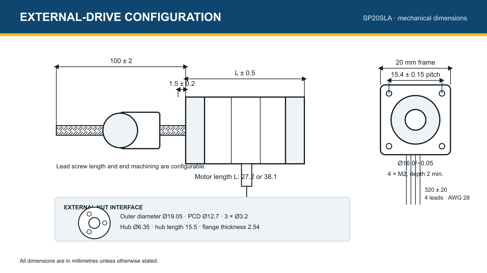
SP20SLA external drive dimensions
External-drive configuration and nut interface.
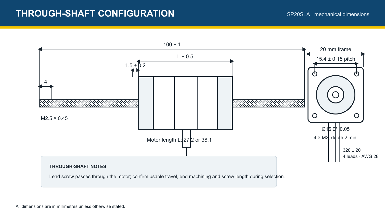
SP20SLA through shaft dimensions
Through-shaft configuration.
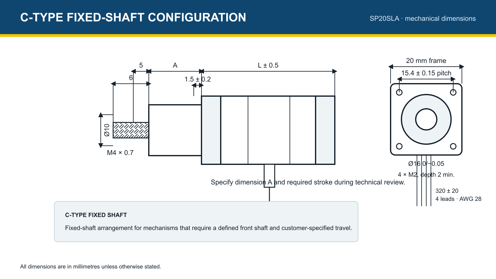
SP20SLA c type fixed shaft dimensions
C-type fixed-shaft configuration.
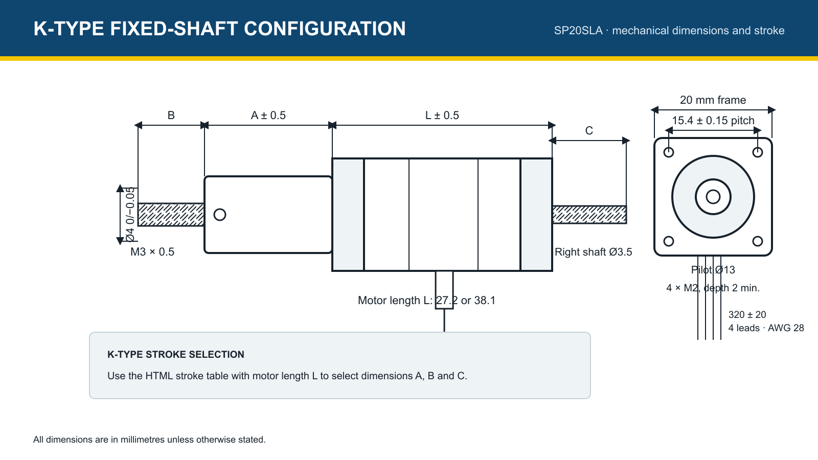
SP20SLA k type fixed shaft dimensions
K-type fixed-shaft configuration.
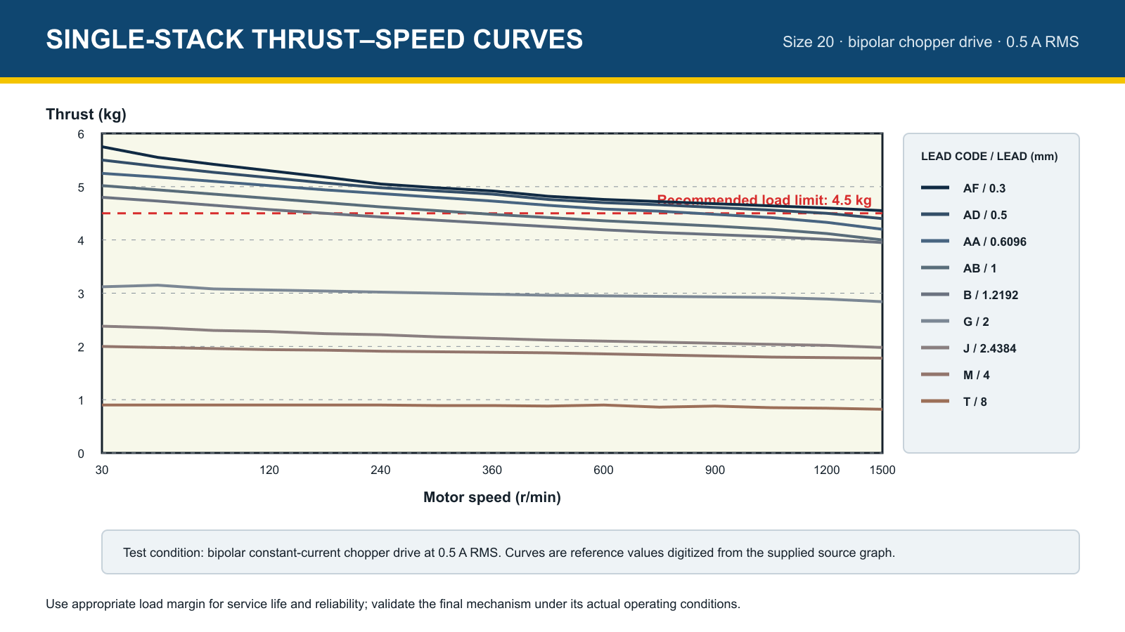
SP20SLA single-stack thrust speed curves
Single-stack reference curves at 0.5 A RMS; recommended load limit 4.5 kg.
SP20SLA double-stack thrust speed curves
Double-stack reference curves at 0.5 A RMS; recommended load limit 4.5 kg.
Mechanical integration

Four formats for different motion architectures

Select the construction according to how the lead screw, nut and moving element are arranged.

  • External drive for a travelling external nut
  • Through shaft for screw access on both sides
  • C-type fixed shaft for customer-defined travel
  • K-type fixed shaft with standard stroke combinations
SP20SLA 20 mm sliding lead screw linear actuator configurations
Configuration options

Adapt the actuator to the mechanism

Lead-screw end machining

Threaded, plain, unmachined and customer-specific ends are available.

Anti-backlash nut

External-drive and through-shaft anti-backlash arrangements can be reviewed.

Encoder feedback

Incremental encoder options are available; confirm resolution and output format.

Electromagnetic brake

Optional 20-series brake: 24 VDC ±5%, 9.6 W, static torque above 0.06 N·m, insulation class B.

Application fields

Designed for compact precision mechanisms

Laboratory automation

Sample handling, dispensing and compact positioning.

Medical instruments

Motion for diagnostic and analytical equipment, subject to system validation.

Optical positioning

Controlled adjustment of lenses, sensors and optical components.

Valves and pumps

Actuation for compact valves, dosing pumps and flow-control assemblies.

Selection information

Define the actuator around the load

Use travel, lead, speed, axial load, motor length and feedback requirements to select the configuration.

Motor frame20 mm
Motor lengths27.2 / 38.1 mm
Phase current0.5 A RMS
Lead options0.3–8 mm
Maximum thrustUp to 70 N

Configure the SP20SLA for your mechanism.

Send stroke, lead, speed, axial load, end machining, feedback and brake requirements for review.

Request consultation  →

Contact us

Would you like to learn more about our solutions?
We would be happy to advise you—personally, competently, and tailored to your requirements.

Perfection in a new dimension

SP20SLA 20 mm Sliding Lead Screw Linear Actuator
20 mm sliding lead screw linear actuator with up to 70 N thrust, 0.3–8 mm lead options, four mechanical configurations, encoder, brake and anti-backlash options.

Further Information

csm walpha vorzugsbaureihen slider 720x490 eaea48abcd

Short delivery times available for selected product configurations.

csm tp plus image 125ef722c4

The TP+ HIGH TORQUE enables maximum torque density and maximum torsional rigidity—ideal for demanding applications with dynamic load changes and high positioning accuracy.

csm tp plus mf flansch korrosion liegend slider 78e8934f42

alpha Advanced Line gearboxes with increased durability and food-grade lubrication available.

csm tp plus ma rmw ritzel zahnstange slider f4c7f6da40

The TP+ for coordinated pinion-rack systems for medium to high requirements. Typical areas of application in wood, plastic, and composite processing, in machining centers, or in automation.

csm cynapse produkseite element slider 08849abb4c

With cynapse® and smart services, you can unleash the full potential of your drive system: sensor data is processed, visualized, and analyzed intelligently. Find out how the combination of gearboxes with cynapse® and our Smart Services can make your digital production faster, safer, and more efficient.

Related products